| | 1400 project update. |  |
|
+9Stubbie Clancy Oz1200Guzzi paulbrice GuzziSteve beetle bahamazoo 2highlander Pete Roper 13 posters |
|
| Author | Message |
|---|
Pete Roper
GRiSO Capo

Posts : 10440
Join date : 2013-05-30
Age : 67
|  Subject: 1400 project update. Subject: 1400 project update.  Sun Apr 28, 2019 6:08 am Sun Apr 28, 2019 6:08 am | |
|
Thought some of you might like an update?
Well, it's been up and running but I've found out I approached it the wrong way. Our previous 1400 in Mark's GRiSO was built using a 1400 crank, barrels and pistons and reworked 1200 heads etc in a 1200 case. With the Stelvio I decided to see if it would be possible to simply swap the 1400 heads, with mods, onto a 1400 engine and slot it in to the Stelvio. The answer in a word is 'No'.
There are simply too many differences, the most of them sensor and trigger related, to make it a simple 'Drop in' and our attempts at designing 'Short Cuts' has simply created more issues making mapping, if not impossible, certainly not worth the time and effort.
Another issue that afflicts the 1400 is that it's capacity takes the condenser system's ability to cope to the very limit of tolerance. Even the Cali 1400 which breathes a lot less well than our engine and will typically spin a lot slower has a history of oil expulsion unless everything, especially break in, is perfect. The 1400 in the GRiSO is simply overwhelming the breather/condenser system and we're loosing oil through the engine, dirtying the TB's and wetting the airbox significantly as well as emptying the sump at an unacceptable rate.
One of the problems all big block Guzzis have suffered from since their capacity was taken over 848cc has been oil expulsion, especially at higher RPM, and since that time the swept volume has increased by over half a litre while the internal volume of the crankcase has increased very little. It's a recipe for exactly the problem we are now encountering! Is it fixable? I have no idea but I'm going to give it my best shot and the first stage will be designing and building a baffle plate to 'Semi dry sump' it. While the 1200 and 1400 don't suffer from the oil pick-up exposure that plagues the V11 series introducing a barrier between the oil and the wind age of the crank as well as offering a surface that particulate matter will stick to by surface tension rather than just spraying onto the surface of the oil in the sump aerating it and whipping it into a frenzy can certainly do no harm and will diminish the amount of particulate matter being passed through the breather system. Whether this will be sufficient given the greater activity in the top end of the 8V and the fact that the breathers run directly from the heads rather than the crankcase itself or the timing chest remains to be seen.
The long and the short of it is that I'm going to have to pull the 1400 out of the Stelvio and start again, building everything into another, 1200, crankcase. This does offer up the possibility though of me coming up with a fix for the stupid lack of a replaceable front main bearing that plagues the 8V's. In the mean time I'll sling the 1200 motor back in it and that is where it will probably stay. Quite simply when I do finalise the 1400 it can be slipped into my GRiSO and the nice thing is that most of the mapping groundwork has already been done for the 'G'.
It's been, and continues to be, a very interesting experiment. Even though it is obviously really pushing at the boundaries of what is possible with the motor, (I find it interesting that none of the other people who claim to have built 1400's with a performance bent, even those claiming much larger capacity and absurd power outputs! Have encountered any problems of this sort! I have to wonder if they ever ride their machines hard or further than five miles!) and it's breather system. For now though I am snowed under with work and have a backlog that I need to work through as well as fixing up my Hydro Cali for sidecar attachment. We'll see if we can sort the breather issue on Mark's GRiSO and after that, hopefully after I've retired, I'll comm back to revisit the 1400 in the Stelvio.
Pete
| |
|
| | |
2highlander
Biondino


Posts : 244
Join date : 2016-09-28
Age : 63
| | Subject: Re: 1400 project update. Sun Apr 28, 2019 4:57 pm | |
| Hi Pete,
the 1400 oil consumption issue is well known here, we already PM-ed concerning this. As I told You, I'm running new 1400 cylinders and pistons in a 1200's crankcase with the 1200's heads. Mapping currently is from a Roland Däs torque-kit-lambda-off-map for the 1200 engine with a raised up CO value of +6. Engine is running fine and smooth so far with no hickups even after cold start. Mapping is temporarily and will be done correctly on Roland's dyno in 2 weeks.
Thanks for this update, I will have a look at my throttlebodies and inside the airbox housing. The transparent airbox-to-atmo pipe is free from oil moisture so far. | |
|
| | |
Pete Roper
GRiSO Capo
Posts : 10440
Join date : 2013-05-30
Age : 67
| | Subject: Re: 1400 project update. Sun Apr 28, 2019 11:44 pm | |
| Well if the oil isn't leaking out the only place it can be going will be through the engine. Since it isn't smoking unduly it's unlikely to be rings or guides which would suggest an almost constant expulsion through the breather system. | |
|
| | |
2highlander
Biondino
Posts : 244
Join date : 2016-09-28
Age : 63
| | Subject: Re: 1400 project update. Mon Apr 29, 2019 5:17 pm | |
| I also think the condenser and breather System is the right approach, I suspect it simply running beyond ist limits. I will see whats going on in my engine after a compression test on chamber and crankcase. I would expect no issues concerning this, as it was before in rollerized stock stage.
Perhaps the solution is to increase the sump volume, similar to the distance ring of my old LeMans or to route the breather hoses through a kind of labyrinth. | |
|
| | |
2highlander
Biondino
Posts : 244
Join date : 2016-09-28
Age : 63
| | Subject: Re: 1400 project update. Fri May 10, 2019 10:43 am | |
| One further update. From the red Guzzi forum I know some guys who also did the 1400 ccm conversion. They seem to have no issues concerning oil consumption. One dealer even pulled the cylinders off from a new 1400 cali, keen on seeing how oil circulation is routed there. Meanwhile I had a glimpse inside the airbox through the inspection hole behind the battery. I found a small sea of oil on the ground, however not big enough for the oil running into the transparent pipe. But what I found is a kind of mayo above and oily moisture around the right snorkel, whereas the left one was clean and mostly dry. TB`s both look quite clean, I've seen much worse ones. Don`t know I am right, but my actual conclusion ist the oil in the airbox may have it`s origin from the blowby system, what other way should it find to the airbox? It`s sucked in from there again, burnt in the engine, blasted to atmo and causes the outlets of the exhausts being black with soot. The next thing I will do is a pressure loss test to exclude pressure will find ist`s way into the crankcase by passing the pistons and rings. I don`t really believe in this because I would expect the oil become fastly darker, it actually looks nearly as clear as just filled in. But if so, this may be the edge where the blowby system begins to fail, I`m really curious of the result. And btw, does someone know the exact routing oft he breather hoses between engine, cooler and airbox? The explosion pics or mech manuals I have don`t help as much for my needs … [You must be registered and logged in to see this image.]
Last edited by 2highlander on Fri May 10, 2019 12:14 pm; edited 1 time in total | |
|
| | |
2highlander
Biondino
Posts : 244
Join date : 2016-09-28
Age : 63
| | Subject: Re: 1400 project update. Fri May 10, 2019 10:44 am | |
| | |
|
| | |
bahamazoo
GRiSO Capo

Posts : 1329
Join date : 2015-08-09
Age : 59
| | Subject: Re: 1400 project update. Fri May 10, 2019 1:29 pm | |
| doesn't help or solve....but my Sport - when it did, always made mayo in the right rocker cover. I'm guessing that as the right pot sits higher when the bike is cooling on the side stand, and the hot oil/water mist rises to the highest point.... | |
|
| | |
2highlander
Biondino
Posts : 244
Join date : 2016-09-28
Age : 63
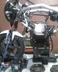
| | Subject: Re: 1400 project update. Fri May 10, 2019 7:13 pm | |
| I checked valve clearances today, they all were till 0.15 mm too wide without any exception! I think the bloke who installed the big bores just bolted them on without readjusting anything! *grzgrmbl [You must be registered and logged in to see this image.] | |
|
| | |
beetle
GRiSO Capo

Posts : 10057
Join date : 2013-09-30
| | Subject: Re: 1400 project update. Sat May 11, 2019 4:01 am | |
| - 2highlander wrote:
And btw, does someone know the exact routing oft he breather hoses between engine, cooler and airbox? The explosion pics or mech manuals I have don`t help as much for my needs … The box drain hose runs straight down, then across valley between the cylinders from near the left barrel, then down the left side of the gearbox, behind the starter, to the sump. The hose to the airbox runs along the inside of the frame on right, and goes across the top of the throttle bodies to the left side of the airbox. The hoses from the valve cover breathers run just below each side of frame, then in behind the coils to the collector box. --- --- --- --- --- --- --- --- --- --- --- --- --- --- --- --- --- --- --- --- --- --- --- --- ..[You must be registered and logged in to see this image.].In GRiSO we trust! . | |
|
| | |
2highlander
Biondino
Posts : 244
Join date : 2016-09-28
Age : 63
| | Subject: Re: 1400 project update. Sun May 12, 2019 10:02 am | |
| Hey beetle, thx for Your forensic explanation. I will investigate and report the actual state. | |
|
| | |
Pete Roper
GRiSO Capo
Posts : 10440
Join date : 2013-05-30
Age : 67
| | Subject: Re: 1400 project update. Sun May 12, 2019 11:55 am | |
| Martin Harvey actually had an interesting idea on WG of using the frame as the collector/condenser. It's not outrageous but is not a system I like as it is replicating the one used on later Tonti's.
Why don't I like it? Because it rusts out the frame and the disgusting mank flows back with the condensate into the sump.
As a last resort it's a possibility but I'd see it as exactly that, a last resort. I'm almost certain the main issue is the volume of the condenser. We have to work to work around that.
Pete | |
|
| | |
beetle
GRiSO Capo
Posts : 10057
Join date : 2013-09-30
| | Subject: Re: 1400 project update. Sun May 12, 2019 12:40 pm | |
|
I've been researching catch cans pretty much non-stop. Finding one to fit is the challenge.
--- --- --- --- --- --- --- --- --- --- --- --- --- --- --- --- --- --- --- --- --- --- --- --- ..[You must be registered and logged in to see this image.].In GRiSO we trust! . | |
|
| | |
GuzziSteve
Fra Cristoforo

Posts : 772
Join date : 2016-04-14
| | Subject: Re: 1400 project update. Sun May 12, 2019 2:57 pm | |
| Tie it to an EVAP canister bracket from USA, plenty of room under trans. | |
|
| | |
paulbrice
GRiSO Capo

Posts : 1481
Join date : 2015-01-04
Age : 63
| | Subject: Re: 1400 project update. Sun May 12, 2019 5:06 pm | |
| I'm doing similar catch can research - I want to fit and see how much oil accumulates - best I can see so far is this [You must be registered and logged in to see this link.] Also thinking to fit a minature one and just empty it every trip ! | |
|
| | |
Oz1200Guzzi
Don Abbondio


Posts : 6081
Join date : 2014-03-13
Age : 69
| | Subject: Re: 1400 project update. Mon May 13, 2019 12:13 am | |
| Thinking outside the box - way back last century when strokers were quite normal, you could get a small plastic tank for the oil injection business. Maybe hunt one of those down - already comes with a drain spigot underneath ( a bit of tube, a plug, easy to drain). Just mount it and put a hole in the lid to drain into. It would work, dunno where you would mount it on a GRiSO though | |
|
| | |
bahamazoo
GRiSO Capo
Posts : 1329
Join date : 2015-08-09
Age : 59
| | Subject: Re: 1400 project update. Mon May 13, 2019 12:41 am | |
| what sort of volume are we talking?? when the Sport was a mayo factory, I whipped up a redirection of the breather dump into a plastic bottle that sat next to the battery in the voluminous space that exists under the seat...  [You must be registered and logged in to see this image.] [You must be registered and logged in to see this image.]I started checking it every day, but relaxed after a while, as it didn't fill up that quickly. The bottle had a squirty spigot, that became the inlet with a short pipe down into bottle. Some charcoal filter foam about 1cm thick (remnant from fish tank filter) -seen here under my thumb- was added for conscience, and then just a hole drilled in top as a breather. The rocker covers collected far less mayo, so I called it a win. | |
|
| | |
beetle
GRiSO Capo
Posts : 10057
Join date : 2013-09-30
| | Subject: Re: 1400 project update. Mon May 13, 2019 1:01 am | |
|
That's the $64 question. The current volume of the GRiSO box is unknown. An autopsy may be required. I can tell you that a wee plastic bottle won't cut the mustard. There's significantly more blow-by with the 1400.
I was considering a second can, but where to put it? Steve's idea is a good one, but it would probably mean it would require manually draining it. I can live with that.
--- --- --- --- --- --- --- --- --- --- --- --- --- --- --- --- --- --- --- --- --- --- --- --- ..[You must be registered and logged in to see this image.].In GRiSO we trust! . | |
|
| | |
Oz1200Guzzi
Don Abbondio
Posts : 6081
Join date : 2014-03-13
Age : 69
| | Subject: Re: 1400 project update. Mon May 13, 2019 1:38 am | |
| Gives you another excuse to do "maintenance/tuning runs". | |
|
| | |
2highlander
Biondino
Posts : 244
Join date : 2016-09-28
Age : 63
| | Subject: Re: 1400 project update. Mon May 13, 2019 8:05 am | |
| Hi folks, Mark's description of the breather hoses routing exactly hits the pic of the spare parts catalogue. [You must be registered and logged in to see this image.]As far as I can say, there are some differences with my 2012 GRiSO. The collector has 4 connections, 2 on each side. The bottom left one straight leads to the sump, the upper one to the left valve cover, so far, so good. And this is where the differences begin. The hose from the collector's upper right side connects to the upper right side of the airbox, the bottom one to the right valve cover. Besides the upper right side connection, the airbox has one more on the left side. There is a hose, describing a loop between the throttle bodies, which finally leads to the stepper. I have no clue why this hose loops and is not connected on the shortest way. As a consequence of having corrected valve clearances I will do a tb balancing this afternoon and in the same way convince myself one more time of being right in my routing description. Boah boys, this nearly leads me to the limits of my English knowledge, hope You all understand my forensics...
Last edited by 2highlander on Mon May 13, 2019 1:19 pm; edited 2 times in total | |
|
| | |
2highlander
Biondino
Posts : 244
Join date : 2016-09-28
Age : 63
| | Subject: Re: 1400 project update. Mon May 13, 2019 8:29 am | |
| Beside the stock one, this is the catchcan of my old LM1 with a 950ccm big bore. It's a fuel tank of a remoted model airplane, it could be worth to do a research on that. [You must be registered and logged in to see this image.]
Last edited by 2highlander on Mon May 13, 2019 11:46 am; edited 1 time in total | |
|
| | |
Clancy
Nibbio


Posts : 754
Join date : 2016-02-10
| | Subject: Re: 1400 project update. Mon May 13, 2019 8:39 am | |
| I rigged up this catch can for my V7-II. It worked well. Probably not helpful to you but..... [You must be registered and logged in to see this image.] | |
|
| | |
paulbrice
GRiSO Capo
Posts : 1481
Join date : 2015-01-04
Age : 63
| | Subject: Re: 1400 project update. Mon May 13, 2019 10:27 am | |
| The plumbing difference point made me wonder if 'wrong connecting' the pipes into collector could by-pass oil dis-engagement & push more oil through to oil box. The stepper air feed from the airbox isn't different (at least to my 2009) as it's pipe 4 here; but it isn't part of the blow-by breather diagram. [You must be registered and logged in to see this image.]& Thanks Clancy - that looks good & very useful to see what it could look like in real life !! BTW I'm thinking catch can would need at least 0.5L and maybe 0.75L & some baffle/tight bends inside to disengage entrained oil mist in high speed air flow.... | |
|
| | |
Pete Roper
GRiSO Capo
Posts : 10440
Join date : 2013-05-30
Age : 67
| | Subject: Re: 1400 project update. Mon May 13, 2019 12:35 pm | |
| Ummm! Is that the picture you wanted to post? | |
|
| | |
2highlander
Biondino
Posts : 244
Join date : 2016-09-28
Age : 63
| | Subject: Re: 1400 project update. Mon May 13, 2019 12:37 pm | |
| Now here's a quick scheme of my GRiSO's breather hoses routing. [You must be registered and logged in to see this image.]What buggers me is that I would have expected the breathers from the cam covers to be connected to the collector symmetrical, both at every upper or bottom fittings. But it seems to be right, the factory clamps seem to be untouched, can someone confirm this?
Last edited by 2highlander on Mon May 13, 2019 1:57 pm; edited 3 times in total | |
|
| | |
2highlander
Biondino
Posts : 244
Join date : 2016-09-28
Age : 63
| | Subject: Re: 1400 project update. Mon May 13, 2019 12:40 pm | |
| - Pete Roper wrote:
- Ummm! Is that the picture you wanted to post?
Yes Pete, I think it's right, he spoke of pipe 4 which connects to the stepper | |
|
| | |
Sponsored content
| | Subject: Re: 1400 project update. | |
| |
|
| | |
| | 1400 project update. | |
|